EN
EN
 AR
AR
 BG
BG
 HR
HR
 CS
CS
 DA
DA
 NL
NL
 FI
FI
 FR
FR
 DE
DE
 EL
EL
 HI
HI
 IT
IT
 JA
JA
 KO
KO
 PL
PL
 PT
PT
 RU
RU
 ES
ES
 SV
SV
 TL
TL
 IW
IW
 ID
ID
 LV
LV
 SR
SR
 UK
UK
 VI
VI
 GL
GL
 HU
HU
 TH
TH
 TR
TR
 AF
AF
 MS
MS
 SW
SW
 GA
GA
 CY
CY
 IS
IS
 BN
BN
 BS
BS
 NE
NE

How to Install Thread Screw Pogo Pin in Device Housing
Installing a thread screw pogo pin in device housing requires precision, proper tools, and understanding of the mechanical tolerances involved. These specialized connectors provide reliable electrical connections while offering secure mechanical attachment through their threaded design. The thread screw pogo pin has become increasingly popular in industrial applications where vibration resistance and long-term durability are critical requirements. Proper installation ensures optimal performance and prevents common issues such as poor electrical contact, mechanical failure, or housing damage during assembly processes.
Understanding Thread Screw Pogo Pin Components
Basic Construction Elements
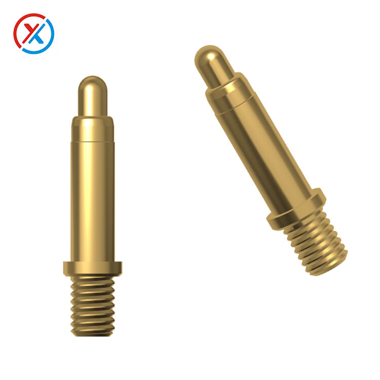
The thread screw pogo pin consists of several critical components that work together to provide both electrical connectivity and mechanical stability. The primary elements include the threaded body, spring-loaded contact pin, insulating sleeve, and retention mechanism. Each component serves a specific function in maintaining electrical continuity while withstanding mechanical stress. The threaded body provides the mounting interface with the device housing, while the spring mechanism ensures consistent contact pressure regardless of minor variations in mating component positioning.
Understanding the material composition is essential for successful installation. Most thread screw pogo pins feature brass or stainless steel bodies with gold-plated contacts to ensure corrosion resistance and optimal electrical performance. The spring mechanism typically utilizes beryllium copper or phosphor bronze for reliable spring characteristics and electrical conductivity. These material choices directly impact the installation requirements and long-term performance characteristics of the connector system.
Dimensional Specifications and Tolerances
Accurate dimensional analysis forms the foundation of successful thread screw pogo pin installation. The connector requires precise hole sizing in the device housing to achieve proper thread engagement without excessive force or inadequate retention. Standard thread pitches range from M2 to M8, with specific tolerances dependent on the application requirements and housing material properties. Understanding these specifications prevents installation issues and ensures reliable mechanical attachment.
Thread engagement length significantly affects the mechanical strength and electrical performance of the installed connector. Insufficient engagement reduces holding strength and may result in loosening under vibration or thermal cycling. Excessive engagement can cause binding or damage to the housing material during installation. Industry standards recommend minimum engagement of 1.5 times the thread diameter for optimal performance in most applications involving thread screw pogo pin assemblies.
Housing Preparation and Tooling Requirements
Hole Drilling and Threading Operations
Preparing the device housing begins with accurate hole placement and drilling operations. The initial pilot hole must be precisely positioned according to the design specifications and electrical routing requirements. Drill bit selection depends on the housing material, with considerations for chip evacuation and surface finish quality. Maintaining proper cutting speeds and feed rates prevents overheating and ensures dimensional accuracy of the prepared hole.
Threading operations require specialized taps matched to the thread screw pogo pin specifications. Thread cutting fluid application reduces friction and prevents galling during the tapping process. Proper tap alignment prevents cross-threading and ensures uniform thread form throughout the engagement length. Hand tapping provides better control for delicate housing materials, while machine tapping offers consistency for high-volume production applications.
Surface Preparation and Cleaning
Surface preparation significantly impacts the electrical and mechanical performance of the installed thread screw pogo pin connection. Thorough cleaning removes machining debris, cutting fluids, and contamination that could interfere with proper seating or electrical continuity. Solvent cleaning followed by dry air purging ensures optimal surface conditions for connector installation and long-term reliability.
Thread inspection verifies proper form and dimensional accuracy before connector installation. Thread gauges confirm proper pitch and major diameter specifications, while visual inspection identifies potential defects such as torn threads or excessive burr formation. Correcting threading issues before installation prevents damage to the thread screw pogo pin and ensures reliable mechanical attachment throughout the product lifecycle.
Installation Procedures and Techniques
Initial Threading and Seating
Beginning the installation process requires careful alignment of the thread screw pogo pin with the prepared housing threads. Manual rotation for the first few turns prevents cross-threading and ensures proper engagement. Applying minimal axial force during initial threading allows the connector to find its natural seating position without forcing misalignment. Resistance to rotation indicates proper thread engagement, while binding suggests potential cross-threading that requires correction.
Progressive tightening using appropriate torque values prevents over-stressing the housing material while ensuring adequate retention force. Torque specifications vary based on housing material, thread size, and application requirements. Under-tightening results in loose connections prone to vibration-induced failure, while over-tightening can strip threads or crack brittle housing materials. Following manufacturer recommendations ensures optimal installation results.
Torque Application and Final Positioning
Proper torque application requires calibrated tools and systematic approach to achieve consistent results. Torque wrenches sized appropriately for the thread screw pogo pin dimensions prevent over-application while ensuring adequate tightening force. Progressive torque application in multiple steps allows stress distribution and prevents sudden failure modes in sensitive housing materials. Final torque verification confirms proper installation and provides baseline values for future maintenance operations.
Final positioning verification ensures the thread screw pogo pin achieves proper electrical contact geometry with mating components. Spring compression measurements verify adequate contact force without excessive pre-loading that could cause premature wear. Electrical continuity testing confirms proper installation and identifies potential issues before system integration. These verification steps prevent field failures and ensure reliable long-term performance.
Quality Control and Testing Procedures
Mechanical Integrity Verification
Comprehensive mechanical testing validates the installation quality and long-term reliability of the thread screw pogo pin assembly. Pull tests verify adequate thread engagement and retention force under specified loading conditions. Vibration testing simulates operational environments to identify potential loosening or fatigue issues. These mechanical validations ensure the connector maintains integrity throughout the expected service life under normal operating conditions.
Torque retention testing evaluates the ability of the threaded connection to maintain proper tightness over time and thermal cycling. Measurement of residual torque after environmental exposure identifies potential relaxation issues that could affect long-term reliability. Regular monitoring during product development phases establishes baseline performance characteristics and identifies optimization opportunities for improved durability.
Electrical Performance Validation
Electrical testing encompasses contact resistance measurements, current carrying capacity verification, and insulation resistance validation. Contact resistance measurements at various compression levels ensure consistent electrical performance across the expected operating range. Current carrying capacity testing validates thermal performance and identifies potential hot spots that could affect reliability. These electrical validations confirm that the installed thread screw pogo pin meets design specifications.
Environmental testing exposes the installed connector to temperature cycling, humidity exposure, and corrosive atmosphere conditions typical of the intended application. Electrical performance monitoring during environmental exposure identifies degradation mechanisms and validates protective coating effectiveness. Long-term stability testing provides confidence in field reliability and supports warranty determinations for the complete assembly.
Troubleshooting Common Installation Issues
Thread Engagement Problems
Cross-threading represents the most common installation problem with thread screw pogo pin connectors. This issue typically results from misalignment during initial threading or excessive force application before proper engagement. Prevention requires careful attention to connector orientation and gradual rotation with minimal axial force until proper thread engagement occurs. Correction often necessitates backing out the connector and starting the threading process again with improved alignment.
Insufficient thread engagement can result from improper hole depth or incorrect tap selection during housing preparation. This condition reduces mechanical strength and may allow loosening under operational stress. Verification of thread depth and engagement length during installation prevents this issue. Correction may require re-machining the housing or selecting alternative thread screw pogo pin variants with different dimensional characteristics.
Electrical Contact Issues
Poor electrical contact often stems from contamination, inadequate spring compression, or improper mating component alignment. Surface contamination from machining operations, handling, or environmental exposure can create high resistance connections or intermittent contact issues. Thorough cleaning of all contact surfaces and proper handling procedures prevent contamination-related problems. Spring compression verification ensures adequate contact force for reliable electrical performance.
Alignment issues between the thread screw pogo pin and mating components can cause excessive wear or inadequate contact area. Proper fixture design and assembly procedures ensure consistent alignment during mating operations. Measurement of contact geometry and wear patterns identifies alignment issues before they cause field failures. Corrective actions may include fixture modifications or adjustment of mating component positioning.
FAQ
What tools are required for proper thread screw pogo pin installation?
Essential tools include precision drill bits matched to the thread size, quality taps for thread cutting, calibrated torque wrenches for proper tightening, and appropriate cutting fluids for smooth threading operations. Thread gauges help verify proper thread form before installation, while electrical testing equipment validates connection quality after installation. Using proper tools ensures consistent installation results and prevents damage to both the connector and housing.
How do you determine the correct torque specification for installation?
Torque specifications depend on several factors including thread size, housing material properties, and application requirements. Manufacturer recommendations provide starting points, but validation testing with actual housing materials confirms optimal values. Generally, torque should be sufficient to prevent loosening under operational vibration while avoiding thread stripping or housing damage. Documentation of successful torque values aids in establishing consistent installation procedures.
What are the most critical factors affecting installation success?
Thread preparation quality significantly impacts installation success, requiring proper hole sizing, accurate threading, and thorough cleaning before connector insertion. Proper alignment during initial threading prevents cross-threading damage, while controlled torque application ensures adequate retention without over-stressing components. Environmental considerations such as temperature and cleanliness during installation also affect long-term reliability and performance characteristics.
How can installation quality be verified after completion?
Installation verification includes mechanical tests such as torque retention and pull strength measurements, electrical tests including contact resistance and continuity verification, and visual inspection for proper seating and alignment. Environmental testing may be appropriate for critical applications to validate performance under operational conditions. Documentation of test results provides baseline data for future maintenance and troubleshooting activities.
Hot News
-
Challenges for Pogo pin manufacturers in the AI era
2023-12-14
-
Teach you how to understand Pogo pin spline structure
2023-12-14
-
What products can Pogo pin be used in?
2023-12-14
-
How to choose Pogo pin connector
2023-12-14