EN
EN
 AR
AR
 BG
BG
 HR
HR
 CS
CS
 DA
DA
 NL
NL
 FI
FI
 FR
FR
 DE
DE
 EL
EL
 HI
HI
 IT
IT
 JA
JA
 KO
KO
 PL
PL
 PT
PT
 RU
RU
 ES
ES
 SV
SV
 TL
TL
 IW
IW
 ID
ID
 LV
LV
 SR
SR
 UK
UK
 VI
VI
 GL
GL
 HU
HU
 TH
TH
 TR
TR
 AF
AF
 MS
MS
 SW
SW
 GA
GA
 CY
CY
 IS
IS
 BN
BN
 BS
BS
 NE
NE

How to Integrate Female Pogo Pin Connector into Small Devices?
Aug 25, 2025
0
How to Integrate Female Pogo Pin Connector into Small Devices
Female pogo pin connectors are compact, spring-loaded components designed to create temporary or permanent electrical connections in small devices. Their ability to deliver reliable power and data transfer in tight spaces makes them ideal for wearables, medical sensors, smart gadgets, and other miniaturized electronics. Integrating a female pogo pin connector into a small device requires careful planning, from selecting the right connector to ensuring proper installation and performance. This guide outlines the step-by-step process for integrating a female pogo pin connector into small devices, highlighting key considerations, best practices, and solutions to common challenges.
Understand the Role of Female Pogo Pin Connector in Small Devices
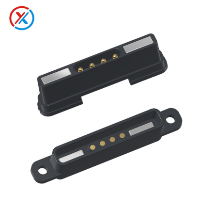
A female pogo pin connector is a receptacle that pairs with a male pogo pin (a spring-loaded pin) to establish an electrical connection. Unlike traditional connectors with fixed pins, pogo pins use a spring mechanism to maintain contact even with slight misalignments or vibrations. This flexibility is critical for small devices, where space is limited and precise alignment during assembly or use can be challenging.
In small devices, female pogo pin connectors serve several key roles:
- Power Delivery: Transferring electrical power to charge batteries or operate components.
- Data Transfer: Sending or receiving data between the device and external tools (e.g., during testing, syncing, or updates).
- Temporary Connections: Enabling easy docking, testing, or maintenance without permanent soldering.
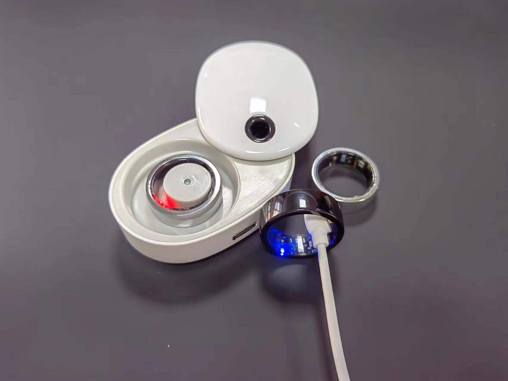
Their small size (often as small as 1–3mm in diameter) and low profile make female pogo pin connectors ideal for devices where space is at a premium, such as smartwatches, fitness trackers, or implantable medical sensors.
Select the Right Female Pogo Pin Connector for Your Device
Choosing the correct female pogo pin connector is the first step in successful integration. Consider these factors to match the connector to your device’s needs:
- Size and Dimensions: Measure the available space in your device to ensure the connector fits without interfering with other components (e.g., batteries, circuit boards, or casings). Female pogo pin connectors come in various lengths and diameters—opt for the smallest size that meets your performance requirements.
- Current and Voltage Ratings: Determine the power needs of your device. Female pogo pin connectors have specific current limits (e.g., 1A, 3A, or 5A) and voltage ratings (e.g., 30V, 50V). Choose a connector that can handle your device’s maximum power draw to avoid overheating or connection failure.
- Number of Pins: Decide how many electrical connections you need. A single-pin connector may suffice for power-only applications, while data-enabled devices may require 2–10 pins for separate power and data lines.
- Spring Force and Contact Reliability: The spring inside the connector determines how firmly it presses against the male pin. Too little force may cause intermittent connections; too much force can wear out the pin or damage the device. Look for connectors with consistent spring force ratings (e.g., 50–200 grams) suitable for your use case.
- Environmental Resistance: If your device will be exposed to moisture, dust, or chemicals (e.g., medical devices or outdoor gadgets), choose a female pogo pin connector with sealing (IP-rated) to prevent damage. Gold plating on contacts also improves corrosion resistance and conductivity.
Consult datasheets from manufacturers (e.g., Molex, TE Connectivity, or Samtec) to compare specifications and ensure the connector meets your device’s requirements.
Design the PCB and Enclosure for Integration
Proper integration of a female pogo pin connector starts with designing the device’s printed circuit board (PCB) and enclosure to accommodate it:
-
PCB Layout:
- Place the female pogo pin connector on the PCB in a location that aligns with the male pin (e.g., on a docking station or test fixture). Ensure there is enough clearance around the connector for the male pin to make contact without obstruction.
- Include solder pads or through-holes on the PCB that match the connector’s pins. Surface-mount technology (SMT) female pogo pin connectors are ideal for small devices, as they sit flat on the PCB and save space.
- Route traces carefully to avoid signal interference, especially if the connector handles both power and data. Separate power and data lines to prevent noise that could disrupt performance.
-
Enclosure Design:
- Create a cutout or recess in the device’s enclosure to expose the female pogo pin connector. The opening should be precise—large enough for the male pin to access the connector but small enough to protect internal components from dust or moisture.
- Ensure the enclosure supports the connector’s alignment. For example, add guides or protrusions on the enclosure to help the male pin align with the female connector during docking.
- If the device is waterproof, use gaskets or seals around the connector’s cutout to maintain the enclosure’s integrity.
3D modeling software (e.g., CAD) can help test the fit of the female pogo pin connector within the PCB and enclosure before prototyping.
Assemble and Mount the Female Pogo Pin Connector
Once the design is finalized, the next step is to mount the female pogo pin connector to the PCB. Follow these best practices for reliable assembly:
-
Soldering:
- For SMT female pogo pin connectors, use a reflow soldering process to attach them to the PCB. This ensures even heat distribution and strong solder joints. Avoid hand soldering unless necessary, as excessive heat can damage the connector’s spring or insulation.
- Inspect solder joints under a microscope to check for cold solder (weak, dull joints) or solder bridges (unwanted connections between pins). These issues can cause short circuits or intermittent connections.
-
Mechanical Mounting:
- Some female pogo pin connectors include mounting tabs or screws for extra stability, especially in devices subject to vibration (e.g., portable tools). Secure these tabs to the PCB or enclosure to prevent the connector from shifting during use.
- Ensure the connector is mounted straight and level. A tilted connector may not align properly with the male pin, leading to poor contact or damage.
-
Testing After Assembly:
- Use a multimeter to test continuity between the connector’s pins and the PCB traces. This confirms the solder joints are strong and conductive.
- Check for short circuits between adjacent pins, which can occur if solder bridges are present.
Proper assembly ensures the female pogo pin connector remains stable and functional throughout the device’s lifespan.
Ensure Alignment and Contact Reliability
Even a well-mounted female pogo pin connector can fail if alignment with the male pin is poor. Take these steps to ensure consistent contact:
- Tolerance for Misalignment: Female pogo pin connectors are designed to tolerate small misalignments (typically ±0.1–0.5mm) due to their spring-loaded design. However, excessive misalignment can cause uneven wear or loss of contact. Design the device and its docking mechanism to minimize misalignment—for example, using guide pins on the docking station to align with holes in the device’s enclosure.
- Contact Pressure Testing: During prototyping, test how varying pressure affects connection reliability. Use a force gauge to measure the pressure required for a stable connection and adjust the spring force of the connector or the design of the docking mechanism accordingly.
- Wear Resistance: Over time, repeated contact between the female pogo pin connector and male pin can wear down the contacts. Choose connectors with durable materials (e.g., gold-plated contacts) to resist wear, and limit the number of connection cycles if possible (e.g., using wireless charging for daily use and pogo pins only for maintenance).
Testing alignment and contact reliability in real-world conditions (e.g., with the device in use or during docking) helps identify issues before mass production.
Test Performance and Durability
After integrating the female pogo pin connector, thorough testing ensures it meets your device’s performance and durability requirements:
-
Electrical Testing:
- Measure voltage drop across the connector during high-current use (e.g., charging) to ensure it does not overheat or lose power. A voltage drop of more than 0.2V may indicate a poor connection.
- Test data transfer speeds (if applicable) to confirm the connector supports the required bandwidth without errors or delays.
-
Environmental Testing:
- Expose the device to temperature extremes (-20°C to 60°C), humidity, or dust to simulate real-world use. Check if the female pogo pin connector maintains contact reliability under these conditions.
- For waterproof devices, perform IP rating tests (e.g., submerging the device in water) to ensure the connector’s seals prevent moisture ingress.
-
Durability Testing:
- Simulate repeated connection cycles (e.g., 10,000+ dockings) to test wear on the connector’s contacts and spring. Check for signs of corrosion, spring fatigue, or reduced conductivity after testing.
Address any issues identified during testing—such as replacing the connector with a higher-rated model or adjusting the alignment mechanism—before finalizing the device design.
Troubleshooting Common Integration Issues
Even with careful planning, challenges may arise when integrating a female pogo pin connector. Here are solutions to common problems:
- Intermittent Connections: This often stems from poor alignment, weak spring force, or dirty contacts. Clean the contacts with isopropyl alcohol, adjust the docking alignment, or replace the connector with one with higher spring force.
- Overheating: Caused by using a connector with a current rating too low for the device. Upgrade to a higher-current female pogo pin connector and ensure the PCB traces can handle the power load.
- Physical Damage: If the connector breaks or shifts during use, reinforce the mounting with additional tabs or adhesive. Choose a connector with a rugged housing (e.g., metal instead of plastic) for devices subject to impact.
- Signal Noise in Data Transfer: This may occur if power and data lines are too close on the PCB. Reroute traces to separate power and data, or use shielded cables in the connector to reduce interference.
FAQ
What is the maximum current a female pogo pin connector can handle?
Most female pogo pin connectors handle 1–5A, but high-power models can support up to 10A. Check the manufacturer’s datasheet for the exact current rating.
Can female pogo pin connectors be used for both power and data?
Yes, multi-pin female pogo pin connectors can separate power and data lines, allowing simultaneous power delivery and data transfer.
How long do female pogo pin connectors last?
With proper use, they can withstand 10,000–100,000 connection cycles. Gold-plated contacts and durable springs extend their lifespan.
Are female pogo pin connectors waterproof?
Some models are IP-rated (e.g., IP67) for water and dust resistance, making them suitable for outdoor or medical devices. Always check the waterproof rating before use.
Can I replace a female pogo pin connector if it fails?
Yes, but replacement requires soldering skills. Design the PCB with easy access to the connector to simplify repairs.
Hot News
-
Challenges for Pogo pin manufacturers in the AI era
2023-12-14
-
Teach you how to understand Pogo pin spline structure
2023-12-14
-
What products can Pogo pin be used in?
2023-12-14
-
How to choose Pogo pin connector
2023-12-14