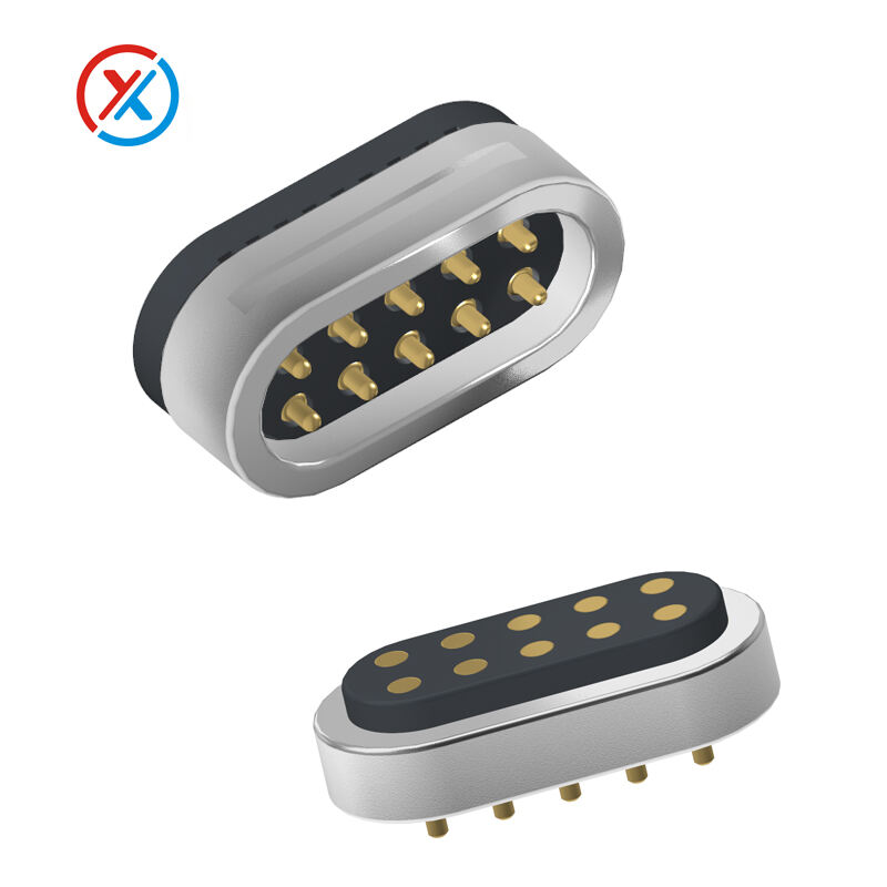
How to Choose the Right 10 Pin Pogo Connector for PCB Design?
Key Specifications for 10 Pin Pogo Connector Selection
Current Rating Requirements for Power and Signal Integrity
Understanding the current rating is critical to ensure that a 10 pin pogo connector efficiently handles the required electrical load without overheating or failing. The current rating informs design considerations, as it must align with the expected operational parameters. Factors such as wire gauge, contact point quality, and ambient temperature significantly influence the current rating. Acknowledging these elements enables precise calculation of the overall energy transmission capacity. Technical data sheets from manufacturers are invaluable, often specifying current ratings between 0.5A to 3A for optimal signal integrity in real-world applications. When selecting connectors, consulting these specifications is essential for establishing reliable performance.
Pitch Dimensions: Balancing Density and Manufacturing Tolerance
Pitch dimensions are pivotal in determining the design and space efficiency of PCB layouts, particularly for high-density applications. Typical pitch sizes, often 2.00 mm or smaller, cater to compact designs while maintaining functionality. Importantly, manufacturing tolerances must be considered to guarantee proper fit and functionality, as variations in PCB fabrication can impact dimensions. Integrating these tolerances ensures the connector does not destabilize or fail due to misalignment. Industry standards offer insights into acceptable tolerances, enabling designs that balance density with manufacturability. For effective connector implementation, these considerations are non-negotiable in maintaining structural and functional integrity.
Optimal Contact Force for Reliable Circuit Board Connections
The contact force of a 10 pin pogo connector must balance ensuring a stable connection and minimizing wear on the connector and PCB. Adequately calibrated contact force prevents intermittent connections and extends the lifetime of circuit components. Utilizing finite element analysis (FEA) allows for detailed testing of stress and wear over time, substantiating findings with empirical accuracy. Industry benchmarks typically recommend contact forces ranging from 50g to 300g, adapting to specific application and environmental needs. Achieving the optimal contact force is crucial in preventing excessive pressure that could compromise connector longevity and performance.
Ensuring Compatibility with PCB Layout Constraints
Space Optimization Strategies for High-Density Designs
Space optimization is crucial in high-density designs, especially when incorporating pogo connectors into PCB layouts. Implementing small footprint designs and strategically reducing the number of PCB layers can significantly enhance available space. Additionally, careful planning of connector placement is vital to avoid signal interference caused by crowded layouts. For effective space utilization, employing simulation software for layout adjustments can provide valuable insights, ensuring alignment with design requirements and enhancing the overall efficiency of the PCB design process.
Footprint Alignment with Existing Component Placement
Aligning the pogo connector's footprint with pre-existing components is essential to avoid extensive redesigns of PCB layouts. Utilizing software tools to meticulously check alignment can drastically reduce errors, streamlining the production process and saving valuable time. Moreover, documenting component placements within layout designs helps validate alignment with industry standards, promoting consistency and reliability in PCB design. This careful planning ensures that new integrations do not disrupt existing arrangements or necessitate cumbersome adjustments.
Thermal Considerations in Vertical/Horizontal Configurations
Thermal management in vertical and horizontal configurations plays a critical role in the performance and longevity of pogo connectors within PCB layouts. The physical configuration of connectors significantly influences heat dissipation patterns across the PCB. By conducting thorough thermal simulations that replicate real-world conditions, engineers can assess and optimize thermal performance, thereby preventing overheating and ensuring stable operation. Case studies from specific design implementations can be referenced to underscore effective thermal management strategies that have been proven in practical applications.
Material Selection and Plating Considerations
Gold vs Nickel Plating: Corrosion Resistance Tradeoffs
Choosing between gold and nickel plating for pogo connectors involves weighing corrosion resistance against cost and mechanical stability. Gold plating is renowned for its superior corrosion resistance, making it ideal for applications in harsh environments where long-term reliability is essential. On the other hand, nickel plating is less expensive and provides considerable mechanical stability, although it may require additional coatings to resist corrosion effectively. Industry studies have shown that gold-plated connectors can increase lifecycle reliability by up to 50% in certain applications, which underscores their value in scenarios where durability is paramount.
Barrel Material Choices for Mechanical Stability
Selecting appropriate barrel materials is crucial to maintain mechanical stability and ensure the longevity of pogo connectors. Commonly used materials include copper alloy and stainless steel, each offering unique benefits suitable for different applications. Copper alloy provides excellent electrical conductivity, while stainless steel is known for its strength and corrosion resistance. The mechanical properties of these materials ensure that pogo connectors remain operational without degradation over time. Data from material performance studies can guide manufacturers in selecting the best material for specific applications, balancing conductivity, strength, and resistance considerations to maximize the connector's effectiveness and reliability in demanding environments.

Evaluating Spring Life Cycle for Long-Term Reliability
Testing Methodologies for 100,000+ Mating Cycles
Establishing rigorous testing methodologies is vital to ensure that pogo connectors can reliably withstand over 100,000 mating cycles. These tests typically involve accelerated life tests such as thermal cycling and endurance testing, which simulate the environmental conditions connectors might face over time. By comprehensively evaluating components under stress, manufacturers can confirm lifecycle claims and optimize their products for long-term reliability. Moreover, collaborating with independent testing labs provides third-party credibility, enhancing the trustworthiness of lifecycle expectations. This meticulous approach not only solidifies confidence in product performance but also aligns with industry standards for durability and efficiency in various applications.
Impact of Vibration and Shock in Harsh Environments
Understanding the reaction of pogo connectors to vibrations and shocks is critical, especially in demanding automotive and aerospace environments. By conducting tests under varying vibration frequencies, manufacturers can simulate real-world conditions and ascertain the reliability of their connectors. These tests reveal how connectors perform under stress, ensuring they can maintain their functions even in shaking environments. Industry case studies often highlight failures caused by inadequate vibration and shock resistance, reinforcing the necessity for robust and thorough testing. This approach not only guarantees product durability but also assures quality in challenging situations, emphasizing the importance of pogo connector reliability in harsh settings.
Customization Options for Specialized PCB Applications
Tailoring Pin Heights for Multi-Board Stacking
Tailoring pin heights is crucial to ensure effective engagement across multiple boards in compact electronic designs. When dealing with multi-board stacking, the precision of pin height can make a significant difference in the performance and reliability of the connectors. Manufacturers can collaborate closely with customers to specify exact requirements, leading to optimal design solutions that meet specific needs. This collaboration promotes functional reliability, reducing risks of misalignment or connectivity issues. Additionally, prototyping these tailored solutions is essential for validating their effectiveness, preventing potential costly errors during production.
OEM Collaboration for Application-Specific Contact Geometry
Working closely with Original Equipment Manufacturers (OEMs) allows for the creation of tailored contact geometries that meet niche application requirements, optimizing functionality and performance. Understanding specific mechanical and electrical parameters is paramount in developing superior connector designs that adhere to stringent industry standards. This collaborative approach ensures that the contact geometry is perfectly aligned with the application, enhancing both reliability and efficiency. Through documenting design iterations and feedback from OEM partners, we can establish a roadmap for ongoing enhancements and future projects, which supports continuous improvement and adaptation to emerging technological trends.
FAQ on 10 Pin Pogo Connector Selection
What factors affect the current rating of a 10 pin pogo connector?
Factors such as wire gauge, contact point quality, and ambient temperature significantly influence the current rating. Acknowledging these elements enables precise calculation of the overall energy transmission capacity.
Why is pitch dimension important for pogo connectors?
Pitch dimension affects design and space efficiency in PCB layouts. It caters to compact designs and must balance density with manufacturing tolerance to maintain functionality in high-density applications.
How can spring lifecycle be evaluated for pogo connectors?
Spring lifecycle can be evaluated using rigorous testing methodologies like thermal cycling and endurance testing to simulate environmental conditions and ascertain durability over 100,000 mating cycles.
Why is collaboration with OEMs important for pogo connectors?
Collaboration with OEMs enables tailored contact geometries suited for niche applications, optimizing functionality, performance, and adherence to stringent industry standards.
Hot News
-
Challenges for Pogo pin manufacturers in the AI era
2023-12-14
-
Teach you how to understand Pogo pin spline structure
2023-12-14
-
What products can Pogo pin be used in?
2023-12-14
-
How to choose Pogo pin connector
2023-12-14

 EN
EN
 AR
AR
 BG
BG
 HR
HR
 CS
CS
 DA
DA
 NL
NL
 FI
FI
 FR
FR
 DE
DE
 EL
EL
 HI
HI
 IT
IT
 JA
JA
 KO
KO
 PL
PL
 PT
PT
 RU
RU
 ES
ES
 SV
SV
 TL
TL
 IW
IW
 ID
ID
 LV
LV
 SR
SR
 UK
UK
 VI
VI
 GL
GL
 HU
HU
 TH
TH
 TR
TR
 AF
AF
 MS
MS
 SW
SW
 GA
GA
 CY
CY
 IS
IS
 BN
BN
 BS
BS
 NE
NE


